

The Refrigeration Cycle is a simple but amazingly clever and useful process.
In its simplest form, the refrigeration cycle consists of just 4 basic components to complete the circuit:
- A Compressor
- A Condenser
- A Restriction
- An Evaporator
That’s it. Well, that’s almost it – we also need a refrigerant to cycle inside the circuit.
As the name suggests, the refrigeration process is a cycle.
We start at the compressor, go through the condenser, then through the restriction, then through the evaporator and finally back to the compressor where the cycle starts all over again.
So let’s have a brief look at each of the components in turn. Luckily, their names are quite self explanatory:
1. The Compressor.
The Compressor can be thought of as the heart of the process.
It acts like a pump to create the circulation by compressing the refrigerant gas, creating a pressure difference that drives the refrigerant around the circuit in a continuous cycle.
2. The Condenser.
The Condenser cools and condenses the refrigerant gas coming from the compressor in to a vapour and finally in to a liquid.
3. The Restriction.
The restriction restricts the liquid refrigerant flow coming from the condenser, and creates a pressure difference between itself and the evaporator. The restriction is more commonly referred to as a METERING DEVICE as it meters the amount of refrigerant entering the evaporator.
4. The Evaporator.
The Evaporator evaporates the liquid refrigerant in to a vapour and then in to a gas before it gets back to the compressor.
5. The Refrigerant.
You may have noticed that in this very brief and simplified introduction to the components, that we have already talked about the refrigerant being a GAS, a VAPOUR and a LIQUID. It is this changing of state within the refrigerant that produces the refrigeration effect, and is the main principle of the refrigeration cycle – more on this a bit later.
Here are some examples of these components and what they look like:
1. The Compressor.
The Compressor is the heart of the refrigeration cycle and comes in a vast array of sizes.
In smaller systems it is usually found inside the outdoor unit, next to the condenser. But in large applications of multiple compressors, like in supermarkets, they are usually found separate inside a covered plant room.


2. The Condenser.
The condenser is often referred to as the ‘outdoor unit’, and that’s usually where you will find it – outdoors, mounted on the floor, wall or roof. In most air conditioning and smaller refrigeration plants, the outdoor unit will house the compressor, condenser, various electronics and in some cases, the restriction (metering device) too. In larger systems the condenser will be a stand alone unit with multiple fans to draw air over the cooling coil.


3. The Restriction (Metering Device).


The vast majority of all modern refrigeration & air conditioning systems will use one of these 3 types of metering device.
Capillary tubes are simply a length of very narrow tube that causes a restriction to the flow of refrigerant.
They are most commonly found on small refrigerators like you have in your home.
Thermostatic Expansion Valves, more commonly termed TEV’s or TXV’s, are very common throughout all refrigeration systems. They use a metal bulb which is partially filled with refrigerant and is strapped to pipe work exiting the evaporator. This bulb matches the temperature of the refrigerant leaving the evaporator, and through pressure can open and close to vary the amount of refrigerant entering the evaporator.
Electronic Expansion Valves, more commonly termed EEV’s or EXV’s, are a more modern and accurate version of a TEV. They are electronically controlled through data provided by an electronic pressure sensor on the pipe work, and can open and close multiple times every second to allow very precise control of the amount of refrigerant entering the evaporator. Being electronic, the data they provide can be examined by refrigeration engineers through software.
To help understand the job of the Restriction or Metering Device, it can be loosely compared to the nozzle on an aerosol spray can.

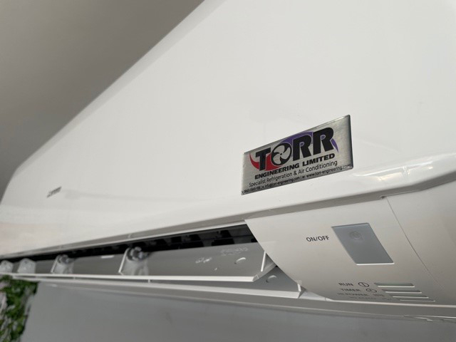
4. The Evaporator.
The Evaporator is often referred to as the ‘indoor unit’, and that’s usually where you will find it – indoors inside the room being cooled (or heated in the case of heat pump air conditioning). They are usually mounted at high level on a ceiling or wall.


The Evaporator & Condenser coils are basically the same type of construction.
A long length of pipe work surrounded by aluminium fins.
They are essentially heat exchangers, similar to the radiator in a car.


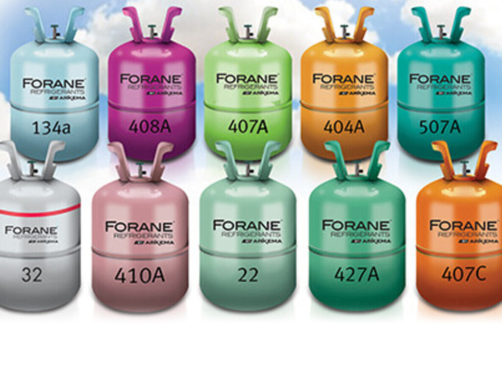
5. The Refrigerant.
There are many types of refrigerants and refrigerant blends. Different refrigerants have different properties to suit the application – Air Conditioning, Cold Rooms, Freezers etc.
Refrigerants are usually referred to by an ‘R’ number, for example R32, R410A, R422D, R507.
Propane (R290), Ammonia (R717), and CO² (R744) are also currently used as refrigerants.


Before we go any further, it’s important to understand what refrigeration actually is:
The term refrigeration means cooling a space, substance or system to lower and/or maintain its temperature below the ambient one (while the removed heat is rejected at a higher temperature). In other words, refrigeration is artificial (human-made) cooling.
Wikipedia.
The important part of this definition is the ‘removed heat ‘.
Something that you perceive as ‘Cold’ is lacking ‘Heat’.
The job of a refrigeration system is simply to remove heat from where it’s not wanted.
Heat is relative – what do you consider hot?
One very important aspect to grasp when understanding the refrigeration cycle is that heat is relative.
We tend to think of heat in terms relative to our everyday experiences and situations.
At 30°C (86°F) we think of it as being a BOILING HOT day! (At least we do here in England!)
When we take a dip in the 16°C (61°F) sea on that hot day it feels FREEZING COLD!
So with a difference of just 14°C (25°F), our perception of heat has gone from BOILING to FREEZING!
But when we look at those temperatures in relation to other temperatures, the reality is very different.
If we look at the temperature of the surface of the sun at 5,500°C (9932°F), our 30°C (86°F)HOT day, in relation, is positively chilly. And likewise, liquid nitrogen at -200°C (-328°F), makes our FREEZING COLD 16°C (61°F) sea seem BOILING HOT!
When we think of the term ‘BOILING’ we instantly think of water in a kettle boiling at 100°C (212°F). We instinctively associate boiling as being 100°C (212°F). But it is important to understand that this only happens with water, at sea level, where the atmospheric pressure is at 1 bar. If we were at the top of mount Everest, where the pressure is only 0.34 bar, our water would ‘boil’ at 71°C (160°F).
The effect of reducing the pressure to reduce the boiling temperature of water is brilliantly demonstrated by boiling water at room temperature by placing the water in a vacuum:
From this it is important to forget your connection of boiling = 100°C (212°F) and think of boiling as being a CHANGE OF STATE from a liquid to a gas. Some refrigerants can ‘boil’ at -40°C (-40°F).
This relationship between PRESSURE & TEMPERATURE is a key factor in the refrigeration cycle process.
The changing of state within the refrigerant, from a liquid to a gas, is achieved by manipulating its pressure.
Under high pressure the refrigerant remains in its liquid state, and when the pressure is reduced the liquid refrigerant begins to ‘boil’ and change in to a vapour or gas.
If we return to the refrigeration cycle with the aid of some diagrams, we can see how these pressure changes causing changes of state within the refrigerant actually happen.
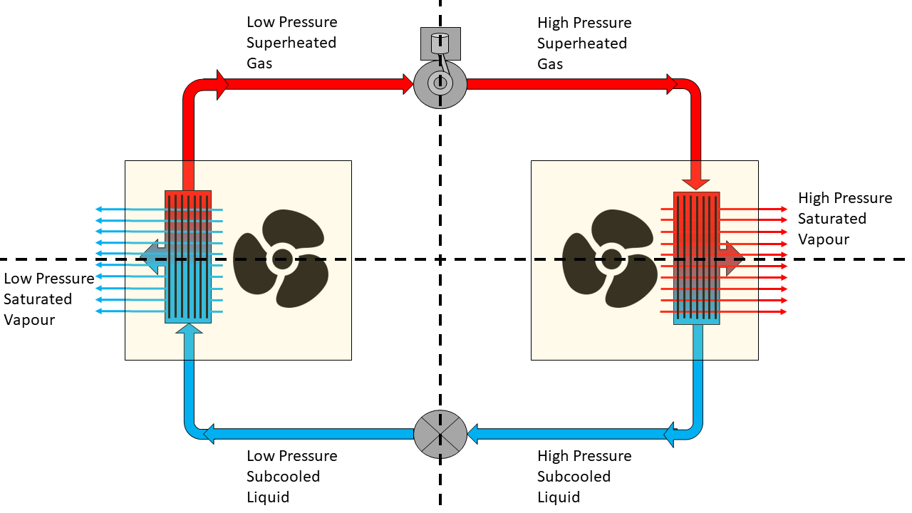
The Refrigeration Cycle – Components:

The Refrigeration Cycle – Flow Direction:

The Refrigeration Cycle – Transfer of Heat:
The heat removed from the air flowing over the evaporator makes it colder. The evaporator fan then blows this colder air back in to the space being cooled.
The heat removed is then rejected by the condenser which is outside of the space being cooled, and usually physically outside in the open air. The fan blows ambient air over the hot condensing coils. This cools and condenses the refrigerant but heats up the air blown over the condenser. That’s why when you stand in front of a condenser it’s usually blowing hot air at you.
The Refrigeration Cycle – Pressures:

The Refrigeration Cycle – Refrigerant State:

In the middle of both the condenser & evaporator, where the change of state of the refrigerant happens, the refrigerant is present in both liquid & gaseous states, and is referred to as a vapour.
The Refrigeration Cycle – Complete:

- SUPERHEAT – Is an amount of heat added to refrigerant vapour beyond its boiling point. This ensures the refrigerant is in a gas state with no liquid present.
- SATURATED – Is just another name for a vapour – when the refrigerant has both liquid & gas present.
- SUBCOOLING – Is an amount of heat removed from the refrigerant below its condensing point. This ensures the refrigerant is in a liquid state with no gas present.
Superheat is important to ensure no liquid makes its way back to the compressor. Although we described the compressor as ‘acting’ like a pump earlier, it isn’t a pump. Pumps usually move liquids by way of an impeller, where as compressors, as the name suggests, compress the volume of the gas which raises both its temperature & pressure. Liquid’s can’t be compressed, and any liquid making its way back to the compressor can cause serious damage.
Subcooling is important as it ensures only pure liquid makes its way to the metering device. This maximises the capacity, efficiency and reliability of the system.
So, looking back at our completed refrigeration cycle diagram, let’s describe the process in full:
- The refrigerant enters the compressor as a low pressure superheated gas.
- The compressor compresses the gas, changing it to a high pressure superheated gas.
- Inside the condenser the gas begins to cool and change state in to a vapour. Additional cooling inside the condenser causes the refrigerant vapour to condense in to a high pressure subcooled liquid.
- As the high pressure liquid refrigerant passes through the metering device it enters a low pressure environment, causing it to flash off and start to vaporise – remember our nozzle on an aerosol spray can example from above?
- The refrigerant vapour enters the evaporator where it absorbs heat from the space being cooled, causing the refrigerant to boil. As it continues through the evaporator coil the vapour is superheated turning the refrigerant to gas before it enters the compressor and starts the cycle over again.
And there it is. THE REFRIGERATION CYCLE in its most basic and understandable terms!
If you’ve made it this far, you probably now have a good understanding of the refrigeration cycle, and we’d love to hear your comments below – Thanks for reading!
For further reading, why not take a look at our article on how the refrigeration cycle makes air conditioning so ENERGY EFFICIENT!


Very informative! As a non-professional, I can clearly figure out parts of a refrigeration system and what they do. Thank you for sharing!
I am trained as an architect and am fairly technically adept; but, honestly, I always get confused about the refrigerant cycle. I have read a bunch of articles like this one over the years, but they never quite stick. This description finally made it clear to me. Thanks! The step by step process you used is very effective.
Thanks for your kind comments Clarke, much appreciated.
This is of course the refrigeration cycle in its simplest form. There are a lot of other components, both electrical & mechanical, that are added to a system in the form of control & safety devices, but no matter how complex a system is, these basic 4 components are the heart of the system and will always be there. If you have that understanding in your head, it makes it easier to comprehend, trace systems out & fault find.
I am in school for HVAC and learning refrigerant. I always get confused about refrigerant cycle. I read alot of articles and still can’t make it stick. Just read this article and able to explain now with no problem and understand refrigerant cycle.
Thanks for your comments Vaughn, glad this little article was able to help you understand and remember the basics of the refrigeration cycle.
I currently taking a course in R & A, this step by step explanation has really helped me to grasp the basics of refrigeration cycle. I will appreciate if you send me a link to download textbooks with practice questions on this subject. Thanks Torr
Hi Ebenezer, when I was studying refrigeration the book I was always recommended and subsequently bought, which was considered ‘the bible’ of refrigeration, was Principles of Refrigeration by Roy J Dossat & Thomas J Horan – more commonly known as just ‘the Dossat’. The book is pretty old but covers the principles of refrigeration which pretty much remain unchanged.
If you google this you should be able to come across copies for sale, but be warned – it’s expensive!
I’m sure you will be able to find more modern books online that will help you with the latest technologies & control systems, but for learning the basic refrigeration principles, the Dossat is a great place to start.
Really loved the article. Great insights.
Thanks for your feedback Priyansh, really appreciated!
Im a f gas trainer and this is how i explain (nearly) ! Il be using some good choice of wording here! Thank you.
Thanks for your comments Andrew, I’m glad you found the article useful and I hope your students do too!
The principles behind the science of refrigeration has alluded me intellectually for years which by no means has slowed down my fascination with the subject.
Now, after reading this article, I can finally connect all the dots as a result of your in depth explanation accompanied with
some very useful diagrams.
There is much to be said of the genius behind this scientific development which really did end up changing the world in a very big way. Necessity was truly the mother of invention in this case, just by the lives it saves in heat related deaths every year alone.
Thank you for your comments Kevin, and you are absolutely correct about how refrigeration revolutionised the world. Not just in its ability to keep people cool, but also in preserving food and in temperature critical industrial processes – including the production of life saving medicines!
Thanks
thanks so much…i have always found the principle of refrigeration very complex but yours was best explained and would stick in for a long time. the pictures were extremely helpful.
Thanks for taking the time to leave your kind comments Denise, glad our little article has helped the basics stick!
Insightful and hope you keep sharing such wonderful information with us
Excellent article. Clear, concise images summarize the text in a very orderly and easy-to-follow manner. Great work, and thank for your time and effort putting it together for our benefit.
Thanks for those kind words gview, glad you found it useful!
As an English teacher in Cuba,sometimes l have to train professionals of different fields,so l have to be informed on their subjects to increase my /their vocabulary…this has been extremely helpful tho l was no total stranger to the topic since l hold l degree in Food Science so thermodinamics was in my curriculum not so deep as engineer level tho,thanks for the valuable insight.
Brilliant Mariano! We’re delighted our article is helping people as far afield as Cuba!
Hi Torr, I teach weatherization students. I am wondering if I have permission to use some of your diagrams. They are great and the explanation is spot on.
I would link it to this website and credit you, of course.
Hi Lara, Thanks for getting in contact regarding your work with weatherization students.
I’m delighted you think our diagrams are useful, and if you think they’ll be beneficial to your students you have our permission to use them, along with a credit back to our article. Thanks!
Here is my question that no one is asking on the internet. When the compressor is compressing the gas into a superheated high-pressure state, it is supplying energy to the gas, which is leading to an increase in temperature thus it is possible for the condenser to reject heat because the temp of the gas is higher than the surroundings and I agree. But when that gas loses heat to the surrounding, shouldn’t that also decrease its pressure, it should no longer be a high-pressure liquid as temperature and pressure are both related to the average kinetic energy. The second confusion is that the liquid formed after the condensation stage is at the same temperature as the outside and thus when it is made into contact with the surrounding in the evaporation stage why should this liquid absorb heat as they both are at the same temperature (why should it expand).
Hi Abi – Good questions!
The temperature of the refrigerant only decreases during the desuperheating and sub-cooling processes, and remains constant during the actual condensing part of the process when the refrigerant is undergoing a change of state from a gas to a liquid. The refrigerant pressure drop over this whole process is relatively small.
When the liquid passes through the restriction or metering device, there is a large pressure drop as the refrigerant gas goes from the discharge (high pressure) side of the compressor circuit to the suction (low pressure) side. This allows the liquid to rapidly expand and change state in to a vapour. This rapid decrease in pressure causes a rapid decrease in temperature of the refrigerant – allowing it to absorb the heat in the space being cooled.
(Think about deodorant in an aerosol spray can – the liquid in the can is stored at high pressure at room temperature, but when you spray it on your body it enters a low pressure environment, rapidly expands in to a vapour, and feels cold on your skin).
This absorption of heat in the evaporator begins to boil the refrigerant vapor, turning it back in to a superheated gas where it then returns back to the compressor to re-start the cycle again.
For a more in-depth and complex answer you may want to read about pressure enthalpy diagrams for the vapour compression cycle, but I hope that answers your question in an understandable way!
Hi,
English is not my mother language. Thus I struggled with this ‘refrigerant’ term.
Refrigerant meaning- the liquid inside the tubes?
Or Refrigerant meaning- the action of refrigerating/ cooling?
Thanks so much for this article.
It is very informative.
Hi Itzi, thanks for commenting.
When we talk about the ‘Refrigerant’, we do mean the liquid inside the tubes as you describe it. Remember though, as the article describes, the refrigerant is not always a liquid – sometimes it’s a vapour and sometimes it’s a gas.
Your diagrams would be better if you made the size of the suction line larger, like they are in reality.
Thanks for your comment Mike, and you are absolutely correct in pointing out that the suction line, in real installations, is larger than the discharge, expansion & liquid lines.
I think people who know that will already be relatively familiar with the refrigeration cycle, and this article was aimed at people with no prior understanding of how the cycle works, and designed to keep things as simple and understandable as possible.
When time permits, I may write a more in-depth article adding some of the additional components to the circuit, a kind of ‘Refrigeration Cycle II’, where I will definitely use your suggestion of showing the different sizes of refrigeration pipe work relative to each other.
Thanks for the informative blog I found your blog very informative keep posting!
Thanks for commenting Priyansh, delighted you find our blog informative!
This article on the refrigeration cycle is an excellent resource for understanding the fundamental principles behind cooling systems. The clear and concise explanations make complex concepts easily graspable for readers like me. It’s fascinating to learn how refrigeration technology works and how it’s essential in our daily lives, from household refrigerators to large-scale industrial cooling applications.
Thanks for those kind comments Teltherm, we’re delighted this little article has helped yet another reader understand the basic concepts of the refrigeration cycle.
Hi there I have searched high and low to try and find out at what rate or frequency does a typical refrigerant go through the whole cycle from gas to liquid ,just ballpark in layman’s terms,IE a 5 KVA electric motor runs refrigeration unit and the system is charged with 1 kilogram of liquid refrigerate ,how many times an hour would that same 1 litre be used over and over again , just approximately guys thanks Russ
Thanks for your question Russ – The answer depends on a number of factors, but as a rough ballpark guide – every 10 to 20 minutes. 3-5 times per hour.
Centered around refrigeration systems, this article elucidates the intricate processes of the refrigeration cycle. It explains compression, condensation, expansion, and evaporation stages in a comprehensible manner. With insightful diagrams and concise descriptions, it’s a valuable resource for grasping the fundamental principles of cooling technology.
this article is very helpful to understand the refrigeration cycle on stages.
Thanks John, glad you found our article helpful!
I have been trying for the past 4 months to build my concept on refrigeration cycle. Unfortunately, I could not find any article that give satisfactory answers to my questions. Luckily, today, I accidentally came across your article and read it almost twice to get it all in my mind. Thank you so much for this kind of article.
Thanks for your reply Naeem, we’re really glad we’ve helped another interested mind grasp the principles of the refrigeration cycle.
This is the best article about refrigeration. It will help us for understanding the refrigeration equipments and latest technology.
thanku so much for this article!
Kind words Komal, thank you, glad it’s helping you understand.
Great article! It seems like pressure is being used to manipulate the boiling point of the refrigerant as it cycles through the system. Would you be against sharing the boiling point of a typical refrigerant used in residential hvac systems as it passes through the condensor coil on the high pressure side and the evaporator coil on the low pressure side? And how does that compare to outdoor and indoor ambient temperature?
Hi Kaushal, thanks for your comments.
There are a lot of variables there, and the answers depend on a number of factors including where in the world you are & the refrigerant being used – I know you say ‘typical’ but typical in the USA is quite different to the typical refrigerant here in England etc.
Danfoss provide a suite of free apps that you can download and experiment with. If you download the ‘REF TOOLS’ app, using the refrigerant slider you will be able to see what pressures refrigerants are at different temperatures etc. Try here: https://www.danfoss.com/en/service-and-support/downloads/dcs/ref-tools/#tab-overview
Hi Torr, stunning teaching you have made something quite difficult easy to understand by using incremental logical steps. Well done and thankyou. Alan
Thanks for that Alan, really appreciate your kind feedback!
Well understood 👏 many thanks to you guys .l am learning a lot.
Thanks for letting us know Junior – Glad our article is helping!
Well explained and well simplified. Examples are on point. Keep on the good work
Kind words – Thank you Kuda!
The detailed explanation helped me grasp the importance of this technology in our daily lives. Grateful for the knowledge shared!
Thank you for taking the time to take us step by step through this cycle. I have linked to your post from a blog that I wrote about geothermal heat pumps, in case people want to better understand how a heat pump can take 55-degree geothermal loops and heat or cool a house with that.
It’s interesting to me that the condenser and the evaporator are essentially the same thing (because the cycle is reversible), yet they tend to have different form factors. In your diagram they look the same, but in practice there are outdoor boxes and indoor “fan coils” or “head units”. Maybe the engineering is different because the indoor ones need to be quieter. Or maybe it’s the same, and the main difference is the outdoor unit has the compressor and pump. I am guessing the latter.
Anyway, thanks again for the careful writeup.
Self explanatory note.
This is one of the best article about refrigeration. Thanks a lot Mr Torr
Thanks for reading and above all replying Mr Aftab – Appreciated!
A brilliant simplification of the Refrigeration process. Thank you for sharing
Kind comments Zeph – Appreciated.
This article provides a comprehensive overview of the refrigeration cycle, explaining the key components and processes involved in cooling systems. It’s a great resource for anyone interested in understanding the science behind refrigeration. Thank you for sharing this informative piece!
Thanks David, we’re glad you found it informative and appreciate you taking the time to say so.
Thank you for sharing all this valuable information!
You’re welcome Tyler, and thanks for taking the time to comment.
I have a question, in the exit of condenser side you have mentioned that the refrigerant must be liquid, is the refrigerant 100% guaranteed changes its phase from saturated vapour to liquid? How?
Hi Michael, thank you for getting in touch with your question.
If a system is functioning properly then yes, when the refrigerant leaves the condenser it will be wholly in a liquid state.
Like we know for a fact that at atmospheric pressure: water (a liquid) will turn to ice (a solid) at temperatures below 0°C, and it will turn to steam (a gas) at temperatures above 100°C, we also know at any given temperature & pressure what state any specific refrigerant will be in.
The thermistors & pressure sensors that monitor the temperature & pressure of the refrigerant in the condensing phase can adjust the condenser fan speed to ensure the refrigerant vapour is subcooled (it’s temperature falls several degrees below the point that vapour can possibly be present at that given pressure) and it is fully condensed in to a liquid.
When a system is not running completely fault free, there may be cases where there is not enough subcooling within the condenser, and some vapour could make its way to the evaporator.
The system will still work, but at a reduced capacity & efficiency. If the fault gets worse for whatever reason (and there are many), the system will get to a point where it doesn’t work at all.
So in brief, under normal circumstances there will be 100% liquid at the expansion valve. Some vapour making its way in to the evaporator will not do any damage but will reduce capacity and efficiency. Preventing liquid from making its way back to the compressor is more important than preventing vapour entering the evaporator because it can cause serious damage. Hope that helps with your question.
The refrigeration cycle is interesting and important. Thanks for sharing!
Great breakdown of the refrigeration cycle – it’s the backbone of every efficient cooling system. At EZaircon, we often educate our clients on how this cycle impacts their aircon’s performance, especially during Singapore’s humid climate. Regular maintenance ensures the refrigerant cycle operates at peak efficiency, reducing energy bills and preventing costly breakdowns. Appreciate this informative post!
Hi, your final descrption says that the refrigerant enters the evaporator as a vapour, so does this mean the Liquid label on the diagram between the metering device and evaporator should say vapour instead? Thanks
Hi Dan, thanks for your question – a good one!
In this article & diagrams, we’ve tried to keep things as simple as possible to help people with no knowledge of the refrigeration cycle understand the basic principles.
In reality there a lots of different types of refrigeration & air conditioning systems, components, configurations & uses.
For instance, most air conditioning systems will have the compressor, condenser & meeting device all contained together in the outdoor unit. The indoor unit (evaporator) could be as far as 70+ metres away from the condenser. In this case the pipe work containing the refrigerant between the metering device & the evaporator is often referred to as an EXPANSION line, rather than a LIQUID line. The refrigerant in the expansion line has already gone through the expansion (metering) device and while there is still liquid present, it is essentially a vapour with both liquid & gas present. The refrigerant is still confined within the relatively narrow pipe work though, so can’t expand further in to gas until it reaches the evaporating unit where it can expand within the additional pipe network in the evaporator coils, and absorb the heat from the room being cooled, turning the refrigerant in to a gas before it returns to the compressor.
We term the states of the refrigerant as ‘Liquid’, ‘Vapour’ & Gas, but obviously as a refrigerant transitions through the vapour stage either evaporating or condensing, there will be differing states of the vapour from almost entirely liquid to almost entirely gas. Before a refrigerant reaches the evaporator, it will be a vapour, but it will be mostly liquid.
Another way to think of it is to imagine a new bottle of refrigerant. There’s no air in the bottle – when the bottle is filled it is vacuumed first to remove all the air, but when you pick up a new bottle of refrigerant it’s not 100% full of liquid. You can feel the liquid sloshing around inside when you shake the bottle. Inside the bottle there will be liquid, vapour and possibly gas too. The refrigerant in all 3 states within the same vessel or environment – But generally we’d refer to it as being liquid.
In terms of refrigeration systems, the metering device is usually very close to the evaporator unit – often inside it, and can be quite literally centimetres away from the coil.
Similar to an air conditioning system like described above, the refrigerant exiting the metering device will be a vapour, but mostly liquid, until it passes through a distribution device – sometimes called a SPIDER because it has lots of legs, where it then enters several different loops of the evaporator coil, and the real expansion starts, allowing the liquid refrigerant to further vaporise and finally turn in to a gas.
Today I was curious on how an air conditioner works. I went down the internet rabbit hole for hours and hours trying to understand the concept. Everything I’ve read and watched up to this point led to other google searches. The thing I couldn’t get my head around is how pressure could change the state of refrigerant. Finally, after reading this article, I get it. Thank you so so much. I wish I started here.
Kind words, thanks for sharing Kevin!
Delighted our little article has helped another interested mind in understanding the refrigeration cycle today.
I disliked thermo – in retrospect likely because I never had good teachers. But I do recall there is a maximum temperature decrease possible in a refrigeration cycle. This came up again this week in on-line posts due to our ~100F temperatures and AC’s struggling to keep up. Remind me (and us) what this is all about. Thanks for your very well written article.
Hi Paul, thanks for your thoughts!
With regard to your question there is no single fixed maximum temperature decrease — it depends on the design and operating conditions of the system.
The minimum evaporator temperature and the maximum condenser temperature are constrained by certain factors though.
The refrigerant cannot condense above its critical temperature, though in practical everyday terms, HVAC system condensing temperatures are usually much lower than their critical temperatures – (often 35–55°C | 95-131°F), depending on ambient conditions and system design. As temperature & pressure are directly linked in the refrigeration cycle, higher temperatures result in higher pressures, and these higher pressures often cause safety devices such as high pressure cut out switches to stop the compressor from working. Necessary both from a physical safety aspect and the protection of the compressor from damage.
So as an example, while the absolute maximum condensing temperature for the common US refrigerant R22 is 96°C | 205°F, in practice systems are designed to run far below that for efficiency and safety.
Similarly, their are limitations to the evaporator part of the system, and a system set too low can regularly ice up causing restricted airflow through the evaporator fins. This can prevent the refrigerant from boiling off from a liquid to a gas, meaning liquid refrigerant makes its way back to the compressor, which can cause serious damage. Therefore, there are also protection devices within the system that will shut it down to prevent this.
Let’s say your typical air conditioning evaporator temperature is 4°C | 39°F and the condensing temperature is 48°C | 118°F, that’s a refrigeration effect difference in temperature of 44°C | 111°F. A statistic or differential that engineers would call Delta Temperature or ΔT. A single-stage vapor-compression cycle is usually limited to about 50–70°C | 122-158°F total temperature drop.
To achieve larger drops (100–200°C | 212-392°F), multi-stage or cascade refrigeration cycles are required.
So in relation to your A/C’s struggling to keep up, if you are evaporator is blowing out at 4°C | 39°F and you have 38°C | 100°F outside ambient temperature, you’re going to have a condensing temperature up around 54°C | 129°F. That’s a ΔT of 50°C | 122°F, and you can see you are getting towards the upper limits of what’s practical & safely achievable in the single stage vapour compression cycle.
Im taking this class for HVAC and this is a lot of valuable information. I for think this is a lot of information though to retain and remember makes it kinda intimidating. But I will keep studying so I can remember it all.
Stick with it Eric, you’ll get there!
I hope this little article helps with the basic fundamentals – re-read it when you need to, and after a few times it will sink in forever!